Reyee Switch PoC Guide V1.0

Please rate this document.
Please leave your suggestions here.
If Ruijie may contact you for more details, please leave your contact information here.
* I understand and agree to Terms of Use and acknowledge Ruijie's Privacy Policy.

Thank you for your feedback!


.Switch Testing Lists
1.1 Management
1.1.1 eWeb
| Testing project | eWeb |
| Testing purpose | Enable WEB and log into switch successfully |
| Testing procedure and expected results |
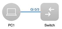
1. Connect PC with switch through net cable as shown above. (in this example, port Gi0/3 is connected) 2. Assign IP 10.44.77.201/24 to PC 3. Enter the default IP of Switch 10.44.77.200 in browser browser must be IE and other major browsers and open compatible mode. 1. Verify Web access. (Expected interface is shown above) |
| Measured record | Login eWeb successfully |
| Testing conclusion | eWeb can be easily opened by simply enter 10.44.77.200 via browser |
| Support Model | All switch series |

1.2 Basic Feature
1.2.1 PoE
| Testing Project | PoE |
| Testing Purpose | Switch can power up AP |
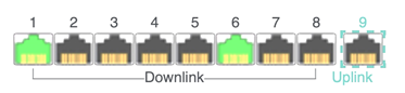
| Testing procedure and expected results | 1. Power on the Switch, connect AP to the switch by net cable
2. Turn on the PoE configuration by clicking the buttons below
PoE switch for each port can be turned on independently
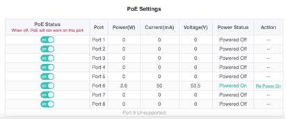
3. PoE interfaces status then can be shown on the top of the webpage. PoE power supply status
|
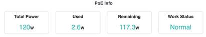
| Measured record | In this case, 2.6W (in port #6) out of 120W is used due to AP connection |
| Testing conclusion |
|
| Support Model | ES205GC-P ES209GC-P ES218GC-P ES226GC-P NBS3100-24GT4SFP-P NBS3100-8GT2SFP-P NBS3200-24GT4XS-P NBS3200-48GT4XS-P |
1.2.2 Access Control List
| Testing project | Access Control List |
| Testing purpose | Create access control list to block access |
| Testing procedure and expected results |
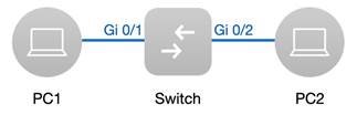
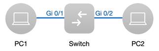
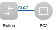
1. Connect PC1 to switch.(In this case, the port is Gi 0/3)
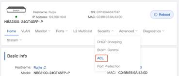
2. Open the ACL configuration via switch eWeb
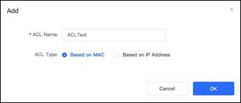
3. Add one ACL based on IP address or MAC then bind with port Gi 0/3
4. Ping 8.8.8.8, Expected results: ping unsuccessfully
5. Unbind ACL with port Gi 0/3 then ping 8.8.8.8 Expected results: ping successfully
|
| Measured record | Once the ACL is removed from port Gi 0/3, access recovers immediately |
| Testing conclusion | When the port is bound with ACL, the access can be effectively blocked |
| Support Model | NBS series |
1.2.3 DHCP Server
| Testing project | DHCP Server |
| Testing purpose | Enable service DHCP and create IP Pool Test to confirm whether each PC can obtain IP address successfully |
| Testing procedure and expected results |
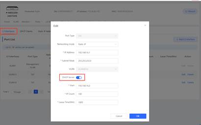
1. Enable DHCP Server via eWeb
2. PC1 and PC2 can obtain IP address. |
| Measured record | PC1 and PC2 can obtain IP address. |
| Testing conclusion | DHCP server can assign IP address to each device successfully. |
| Support Model | NBS 5000 series |
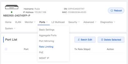
1.2.4 Speed Rate Limiting
| Testing project | Speed Rate Limiting |
| Testing purpose | Set speed rate limits on port then perform the speed test to check speed |
| Testing procedure and expected results |
1. Open Rate limiting configuration page from Port Menu.
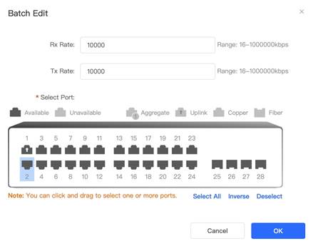
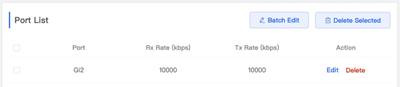
2. Click Batch Edit button to enter speed rate limits configuration interface. Select ports then set Rx Rate and Tx Rate, then click OK In this example, 10000kbps is set for both Rx Rate and Tx Rate. Note that 10000kbps is roughly about 10mbps. When above configuration is done, we can see the port list as shown below. (In this example, port Gi2 is set with rate limiting)
3 Perform the speed test via https://www.speedtest.net Expected results: Speed is limited successfully |
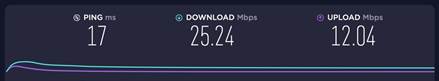
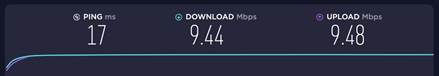
| Measured record | The speed without rate limiting is show below.
With speed rate limiting, we can see that the speed now is limited as we expected. Note that the speed rate limit we set is around 10mbps.
|
| Testing conclusion | With speed rate limiting configuration, the speed can be effectively limited |
| Support Model | NBS series |
1.2.5 Long DistanceTransmission
| Testing project | Long Distance Transmission |
| Testing purpose | Make sure the device can be power on with a long distance transmission. |
| Testing procedure and expected results |
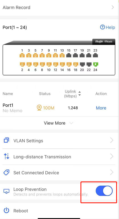
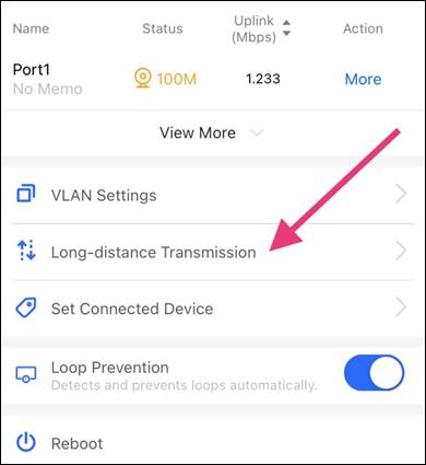
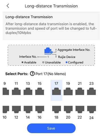
1. Long-distance Transmission feature can be configured via Ruijie Cloud App on your phone
2. Select ports to turn on Long-distance transmission, then press save In this example, port 17 is set for Long-distance Transmission.
3. Confirm whether IP Camera is powered on Expected results: IP Camera is powered on normally |
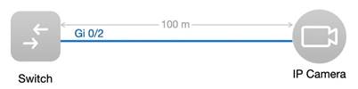
| Measured record | With Long-distance Transmission enabled, the IP Camera can be powered on even it has a distance 100m away from Reyee Switch |
| Testing conclusion | Long-distance Transmission feature can successfully power on the IP Camera with 100 meters |
| Support Model | ESW and NBS series and support PoE models |
1.2.6 Aggregate Port
| Testing project | Aggregate Port |
| Testing purpose | Create aggregate port and check the bandwidth of aggregate port |
| Testing procedure and expected results |
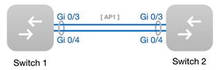
1. The example tropology is shown above. (In this example, switch 1 refers to Reyee switch, switch 2 is typical Ruijie switch)
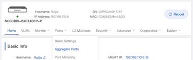
2. Open Switch 1 Aggregate Port configuration from Port’s menu via eWeb as shown below
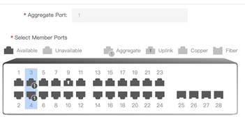
3. Select ports and set them as aggregate port 1. (In this case, port 3 and 4 are selected) Note: Reyee switches only support static aggregation now
4. If both side are Reyee NBS switches, configure them on eWeb are ok 5. Add the following configuration on Ruijie switch SW2>enable SW2#configure terminal SW2(config)#interface range gigabitEthernet 0/3-4 SW2(config-if-range)#port-group 1 SW2(config-if-range)#exit SW2(config)#interface aggregateport 1 SW2(config-if-AggregatePort 1)#switchport mode trunk SW2(config-if-AggregatePort 1)#exit SW2(config)#aggregateport load-balance src-mac SW2(config)#exit SW2#wr 6. Execute command ‘show int agg 1’ to check the bandwidth of the Aggregate port 1 7. Connect a laptop to the switch downstream and continue to ping, unplug a line from the aggregation port, and observe the ping status |
| Measured record | The ping will not disconnect |
| Testing conclusion | NBS series support aggregate port |
| Support Model | NBS series |
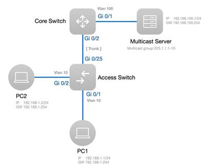
1.2.7 IGMPSnooping
| Testing project | IGMP snooping |
| Testing purpose | Enable IGMP snooping. |
| Testing procedure and expected results |
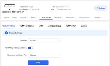
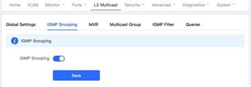
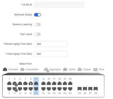
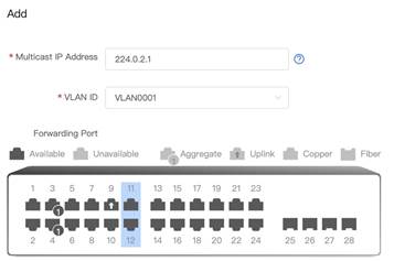
The typical topology is shown above. 1. Enable IGMP Report Suppression and save in the global settings For Unknown Multicast Pkt, Discard is recommended. (Example is shown below) 2. Enable IGMP Snooping and save 3. Set up the following settings Add VLAN for multicast traffic Multicast status: on (mandatory) Dynamic Learning: off Select port members (mandatory) (In this example, port 11 and 12 are selected.)
Remark: When no ports are selected, IGMP Snooping will be stopped. 4. Add specific vlan for multicast and define multicast IP Address and choose ports
In this example, port 11 and 12 are selected.
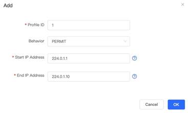
5. When multicast packet is detected by switch, there will be a list in the querier table 6. Define Profile ID, multicast IP range then set Behavior with permit |
| Measured record | Status of IGMP Snooping is enabled on port Gi11 and Gi12 for VLAN 1 |
| Testing conclusion | IGMP Snooping feature can be easily set on Reyee Switch on eWeb |
| Support Model | NBS series |
1.3Security Features
1.3.1 Port Protection
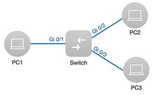
| Testing project | Port Protection |
| Testing purpose | Enable port protect, then test the connection between different ports |
| Testing procedure and expected results |
1. Assign IP 192.168.0.1/24 to PC1 IP 192.168.0.2/24 to PC2 IP 192.168.0.3/24 to PC3
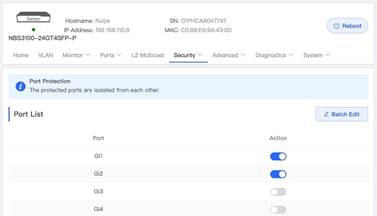
2. Turn on Port Protection on Port Gi1 and Gi2 via eWeb. (The example is shown below)
3. PC1 ping PC2 Expected results: ping unsuccessfully PC1 ping PC3 Expected results: ping successfully PC2 ping PC3 Expected results: ping successfully |
| Measured record | After port Gi1 and Gi2 are set with port protection mode, the communication between PC1 and PC2 are then restricted. |
| Testing conclusion | The feature of Port Protection are effectively prevent interfaces from communicating with each other. |
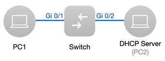
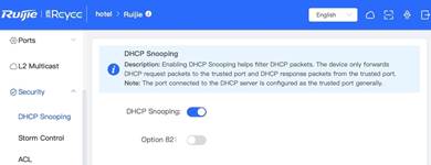
1.3.2 DHCPSnooping
| Testing project | DHCP Snooping |
| Testing purpose | Enable DHCP snooping and PC can obtain the correct IP address |
| Testing procedure and expected results |
1. Assign IP 192.168.0.2/24 to PC2(DHCP Server)
2. Enable DHCP Snooping from eWEB
3. Check whether PC1 can obtain IP address (ipconfig/renew) Expected results: PC1 obtains IP unsuccessfully
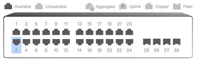
4. Configure the port connected to DHCP server as DHCP Snooping trusted port. (In this example, port Gi2 is set as trusted port)
5. Now PC1 can obtain IP address (ipconfig/renew) Expected results: PC1 obtains IP successfully |
| Measured record | PC1 can obtain IP address successfully after configure the corresponding port as trusted port |
| Testing conclusion | DHCP Snooping can effectively block the packets send from untrusted DHCP server until the corresponding port set as trusted one |
| Support Model | RG-ES216GC RG-ES224GC RG-ES226GC-P RG-ES218GC-P NBS series |
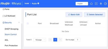
1.3.3 StormControl
| Testing project | Storm Control |
| Testing purpose | Enable Storm Control and LAN Storm Attacks can be prevented by setting traffic rate-limit on ports |
| Testing procedure and expected results |
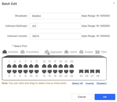
1. Open Storm Control configuration page from Security Menu
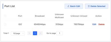
2. Click Batch Edit button to set rate-limit for broadcast, Unknow Multicast and Unknown Unicast, then click OK In this example, storm control is set on port Gi 0/2, the rate-limit for each type of information transfer is shown below. When above configuration is done, we can see the port list as shown below. (In this example, port Gi2 is set with storm control)
3. Simulate a broadcast storm from PC2. (Note: The port Gi2 on switch is connected to PC2) Expected results: Switch controls broadcast storm successfully |
| Measured record | The broadcast storm attack acting on Port Gi2 on switch can be prevented by setting the traffic rate-limit on this port |
| Testing conclusion | Storm Control can effectively prevent the LAN Storm Attacks by configuring traffic rate-limit on the specific ports |
| Support Model | NBS series |
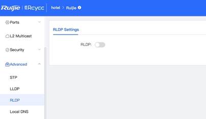
1.3.4 RLDP
| Testing project | RLDP (Rapid Link Detection Protocol) |
| Testing purpose | Enable RLDP to activate rapid link detection regarding to loop trouble |
| Testing procedure and expected results |
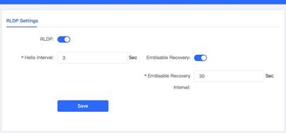
1. Open RLDP configuration page from Advanced Menu. 2. Turn on RLDP with Errdisable Recovery enabled, then click save. In this example, 3 Sec is set for Hello Interval and 30 Sec is set for Errdisable Recovery interval.
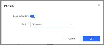
3. Enable Loop Detection by selecting one port from Port List in RLDP Management menu In this example, port Gi2 is selected for Loop Detection
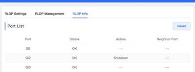
4. At this moment, the port status can be checked in the RLDP Info menu 5. Simulate a loop from PC2 (Note: The port Gi2 on switch is connected to PC2) Expected results: Loop is detected and Port Gi2 shuts down successfully
1. Add the switch to Ruijie cloud and make sure it is online 2. Open the Ruijie Cloud APP and access the account 3. Enable the RLDP on Ruijie Cloud APP
4. A UTP cable is connected to the 2 ports of the switch 5. Check the port status, one of the port will shutdown |
| Measured record | The loop is detected and Port Gi2 shuts down successfully by activating RLDP feature on this port |
| Testing conclusion | Reyee Switch can rapidly detect loop by setting RLDP with specific ports, the ports encountered with loop will be warned, blocked or shut down |
| Support Model | ESW and NBS series |